Reserve space for utilities, replenishment and service before fixing the equipment positions of a tissue converting line. A machine footprint is only one part of the installation drawing. The factory also needs an agreed route for parent rolls and packing material, access to equipment and clearly assigned service connections. DOUBLE's line descriptions leave final layout and utilities subject to the selected configuration. Use those project documents to plan the site, rather than treating a catalogue illustration as a complete floor-space requirement.
Begin with the factory drawing, not a line photograph
Provide a measured site plan showing columns, walls, doors, floor-level changes and fixed services. Identify the area actually available for the project, including restrictions imposed by existing production. Give the equipment supplier one drawing revision to work from. A proposed line can appear to fit an empty rectangle while conflicting with a real column or the route used to bring materials into the building.
Mark the receiving route from the unloading point to the intended machine positions. Ask the supplier for the shipment and installation information needed to review that route, including the dimensions and handling conditions of delivered sections. Do not use assembled machine dimensions as a substitute for a reviewed delivery plan. The local installer should assess the building and handling requirements within its own responsibility.
Include the intended entry and exit points of production material. Parent rolls, packing film, cartons and finished goods may use different routes. The drawing should distinguish them from pedestrian access. Set the actual separations and site controls through the supplier and the responsible local professionals; there is no universal clearance value established by this article.
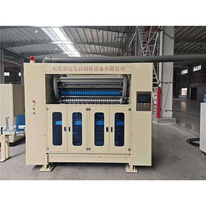
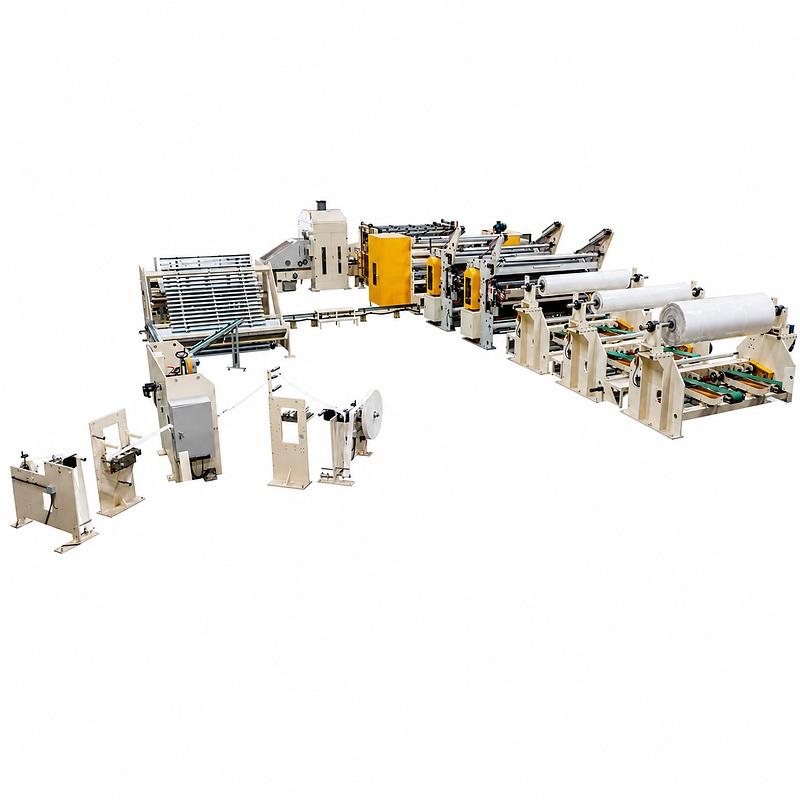
The hand towel line gallery shows workshop context. It is not a layout drawing or a verified installation of the proposed facial tissue line.
Draw the working areas around the equipment
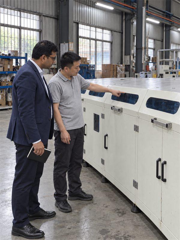
Ask the supplier to show the operator side, replenishment positions and intended maintenance access on the layout. Include the space used when a door, guard or cabinet is opened under the approved procedure. The line descriptions call for access to folding, cutting and packing sections. They do not give a single service distance that can be copied around every machine.
Review parent-roll and film replacement as separate activities. A clear walkway beside the line does not by itself establish that a replacement roll can reach its loading position. Ask which handling equipment is assumed and where the material waits before use. Keep temporary storage outside the access areas agreed for the machine and its electrical equipment.
Identify parts that may need removal during service, then ask the supplier for the required removal direction and handling envelope. This is a planning request, not an instruction to remove a blade or bypass guarding. Authorized personnel need the equipment's own isolation and service procedures. The layout should leave the reviewed task physically possible without relying on moving an unrelated machine.
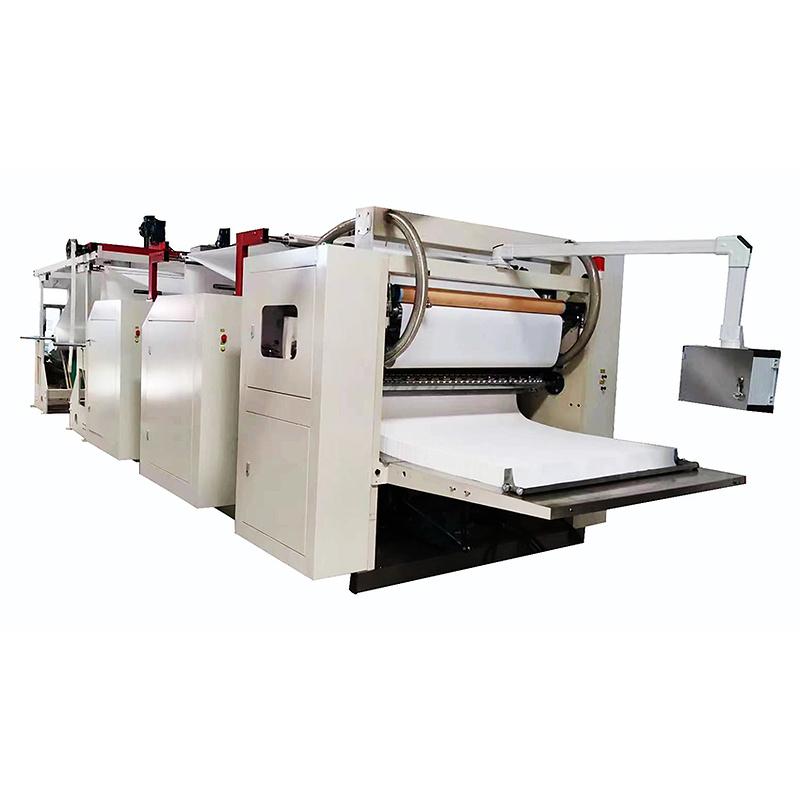
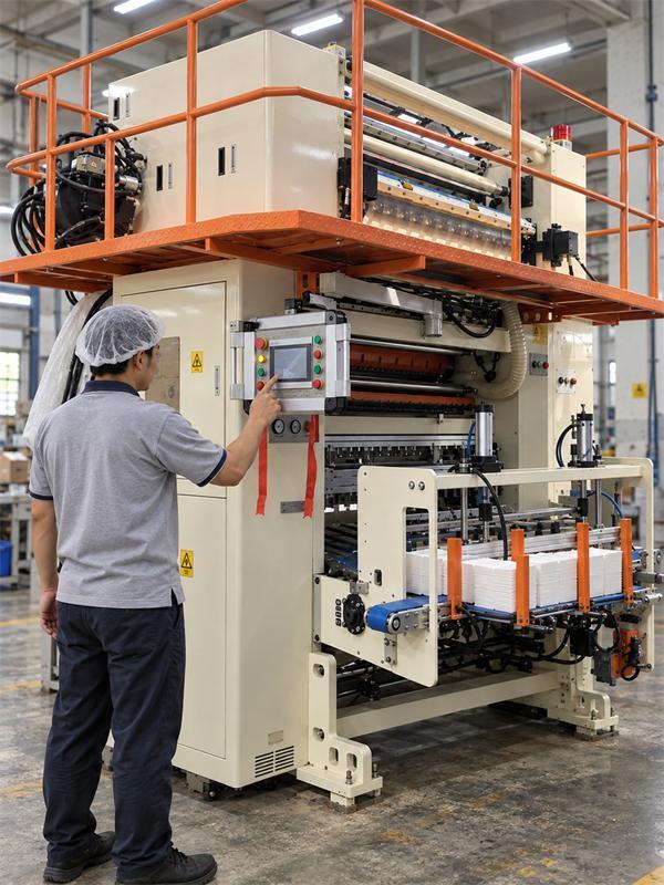
The folding equipment view illustrates why the assembled outline and surrounding working areas need separate drawing information.
Assign each utility connection to a responsible party
Build a connection schedule from the selected machines and line configuration. Request the required electrical supply, compressed-air conditions and any other service specifically identified for the order. Distinguish installed equipment ratings from the site supply design. The supplier's confirmed requirements and the local engineering review should determine the latter.
Interface
Supplier document to request
Buyer-side decision to assign
Electrical supply
Confirmed supply requirements and connection locations
Design, installation and verification of the site supply
Compressed air
Required conditions and connection points for the selected sections
Available service capacity and distribution to those points
Controls between supplied equipment
Included connection scope and interface description
Ownership of links to equipment outside that scope
Material access
Loading positions and approved working areas
Factory routes, storage positions and handling arrangements
Give the physical boundary a name. For example, identify whether the buyer brings a service to a designated connection point or whether a distribution item is included in the supplier's scope. Record who provides fittings, connections and verification where relevant. “Air provided by buyer” is incomplete if neither side has identified where the buyer's work ends.
Do not total unrelated catalogue figures and call the result an approved line requirement. Packing-machine quantity and optional equipment can change the configuration. Request an updated schedule when those decisions change. This prevents an early planning allowance from being treated as a confirmed specification after the line scope has grown.
Review service routes alongside operator access
Place proposed service routes on the same drawing as the equipment and working areas. Ask the installation team to review whether cable or pipe routes interfere with movement, doors or the approved service envelope. Confirm the permitted routing and protection through the responsible professionals. A convenient connection location on paper may conflict with the actual use of that space.
Identify accessible service points for inspection and isolation under the supplied procedures. The layout review should include their position without inventing electrical or pneumatic design instructions. If the building already has a service distribution system, provide its relevant verified details to the installer and supplier. Its presence does not prove that it meets the new line's requirement.
Show electrical cabinets and their access separately from the production infeed. Ask the supplier which cabinet locations are fixed and which can be reviewed for the project. Have the responsible electrical designer confirm the working area and cable approach. Do not use that area for cartons, a film trolley or future equipment merely because it appears empty in the operating layout.
If a utility comes from above or below the equipment, mark the agreed entry point and route before the site contractor starts work. Confirm what drawing information the contractor needs and which details remain provisional. That avoids treating an approximate sketch as an instruction to install a permanent connection. The equipment supplier's connection document and the local contractor's service drawing should refer to the same physical point.
Where extraction, waste handling or another building service is proposed, identify why it is required and who specifies it. Do not automatically add it as a claimed feature of every line. The project record should separate confirmed equipment requirements from facilities the buyer chooses to provide for its own operation.
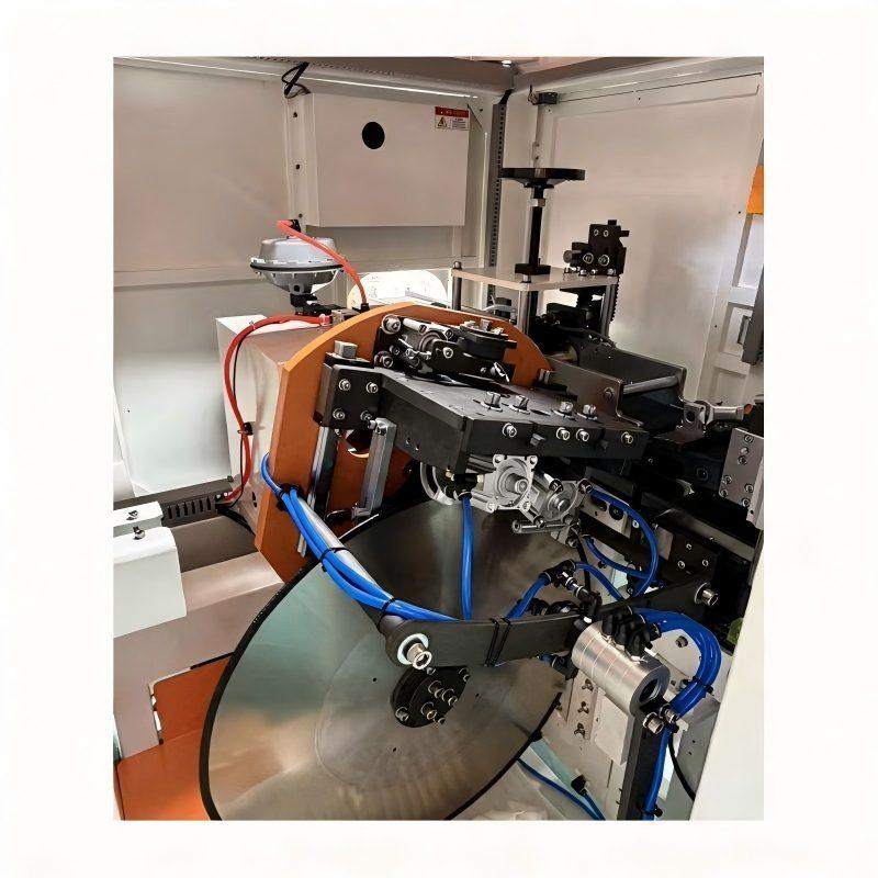
This published machinery detail provides context for service planning. It does not establish a connection specification or permission to access operating equipment.
Reserve the space for the actual end-of-line scope
DOUBLE's soft-pack facial tissue line identifies bundle packing as optional. Its hand towel line has its own transfer and full-seal packing arrangement, while the referenced napkin line includes cartoning and palletizing. These are different spatial scopes. Do not take the main-process area from one line and use it as the complete area for another product.
If outer handling is included, show empty packaging supplies, completed packs or cartons and the removal route. Ask the supplier to mark the guarded or controlled area associated with included equipment. Have the responsible site team review the resulting plan. A finished pallet location, for example, must be considered together with how it will be collected rather than drawn as an isolated rectangle.
Future equipment should be shown as a separate allowance with a stated purpose. Leaving an unlabelled gap does not establish that another packing unit will fit there or connect to the current layout. If expansion is a requirement, ask for the relevant interfaces and assumptions to be reviewed now, without claiming that unselected equipment is already engineered into the order.
Keep the drawings and responsibility list on one revision
Link the approved layout, utility schedule and installation scope by revision date. Name the person who authorizes a relocation or service change. If a conveyor is rerouted, review the affected access and connection points rather than updating only its outline. Send the revision to the machinery supplier and the site team working from the plan.
After positioning, have the responsible installation team record any difference from the approved drawing. Update the site documents before those differences become the basis for later maintenance or expansion. Keep superseded versions available for comparison, but identify the current drawing clearly so that a contractor does not restore an earlier route by mistake.
Ask the automatic soft-pack facial tissue production line proposal to identify unresolved site inputs before installation is scheduled. Close those items through the responsible party's documents and review. A coordinated installation package gives the buyer usable equipment positions, service boundaries and access arrangements; a machine photograph supplies none of those dimensions on its own. It also identifies who must resolve changes before site work continues.




 Tel: +8613908196540
 Email: info@doubletissuemachine.com
 MP/WhatsApp: +8613908196540
 Manufacturer Address:Dongguan, Guangdong, China